The coolant chiller
2009-06-25 19:52 by Ian
For doing distillations and extractions using solvents with low boiling points (such as diethyl ether or chloroform), the coolant in the condenser must be below the temperature of tap water. It also needs to be more stable than an ice-bath.
Here is my construction log of my solution to the problem of reliable sub-zero cooling…
I decided to use a thermoelectric element to cool an aluminum cylinder full of acetone.
This is the inner cylinder of the chiller, shown with a tennis ball for scale. The internal volume of the cylinder is about one liter. Construction is almost entirely aluminum, exempting the 12 steel screws and the 2 brass hose barbs. The wall-thickness is 0.25”. Total mass is 1.5 kilograms.
Here is a closeup of the coolant cap before I drilled it. As you can see, I’ve grooved the surface to increase the surface area (and because I like using the lathe).
And a picture of the mounted coolant cap. This part isn’t quite done. I need to obtain the thermoelectric cooling element and sandwich it between the cap and an aluminum backplane. And that means I need to drill and tap more holes. The counter-sinking wasn’t really necessary on this cap, as it will be covered by the heatsink anyway.
Here is a closeup of the mounted flow cap. Note the counter-sunk screws!
Update 2009.07.17:
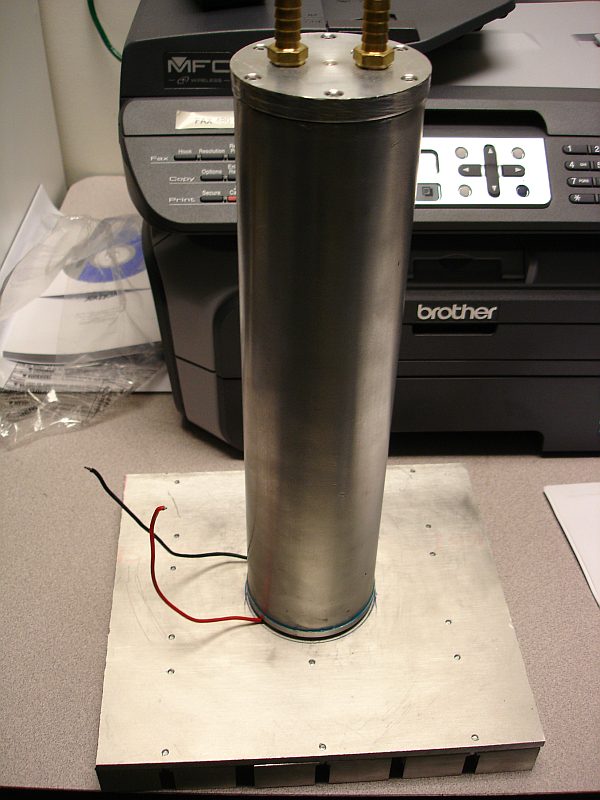
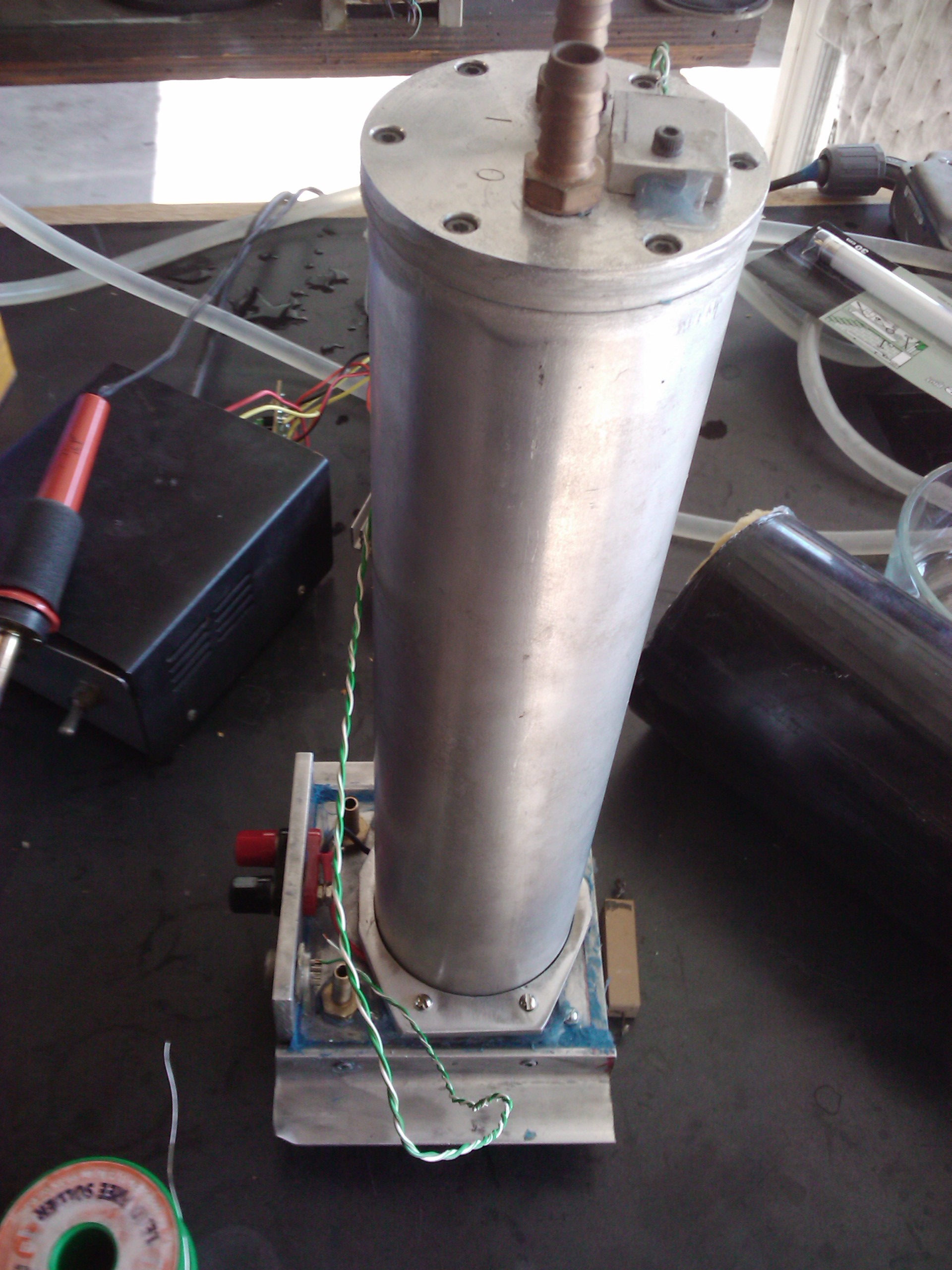
A few more hours in the garage after the TECs arrived, and this project is completed. Here is the completed unit standing upright. Total mass is 3.78kg.
The bottom of the heat sink. This thing has to dissipate 400 watts of heat. Active cooling will be required. I’m thinking of enclosing the heat sink in a water bath to double as a steam generator. Once I start shoving 26 amps through that poor little TEC, it will boil water for sure. At what rate remains to be determined.
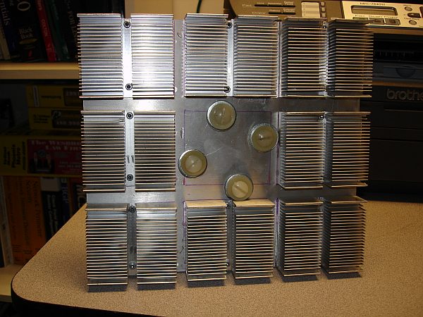
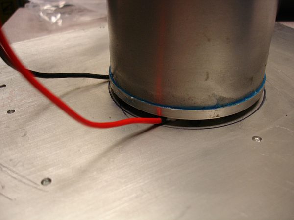
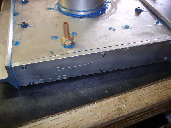
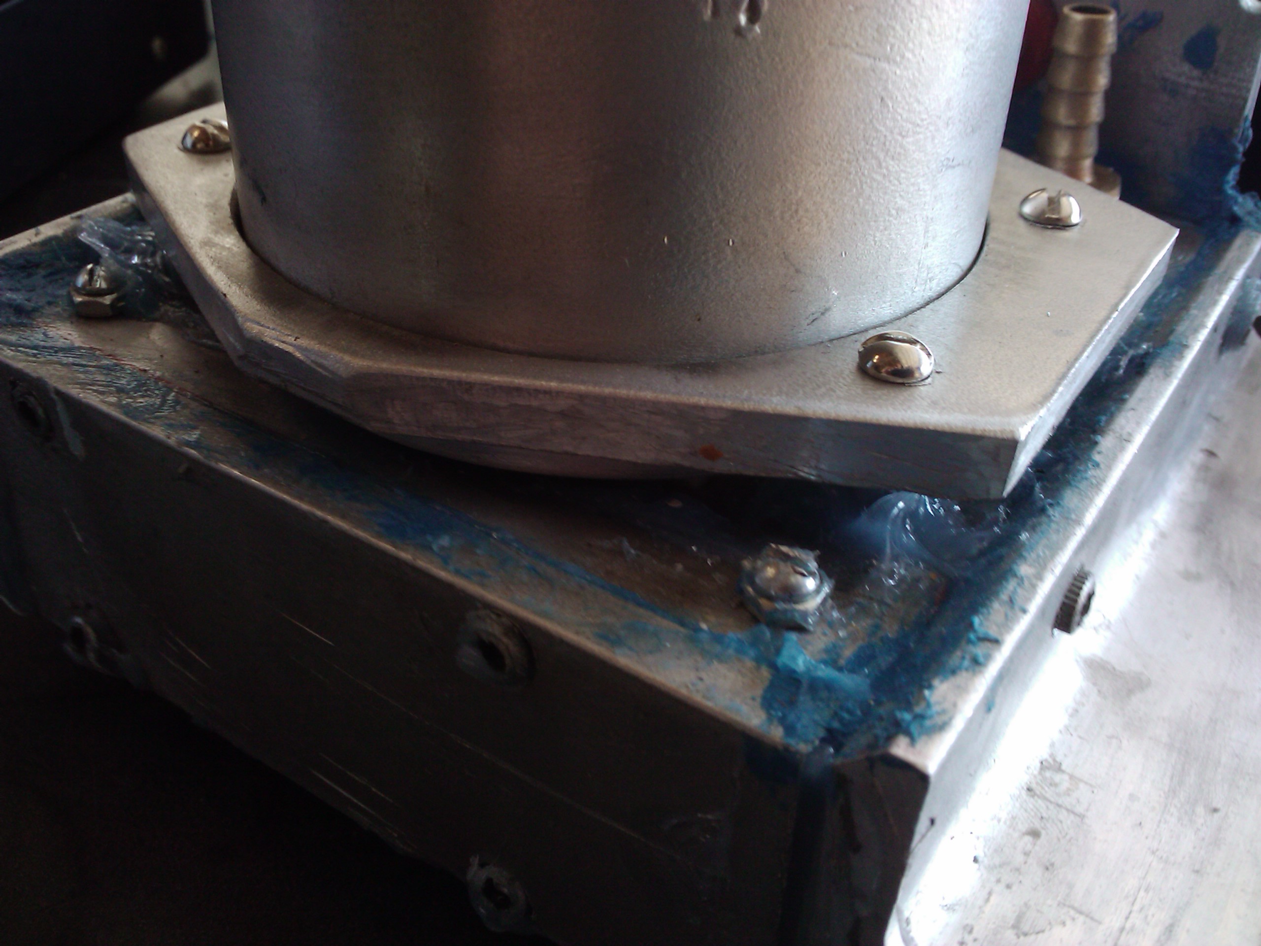
This is a closeup of the interface between the coolant vessel and the heat sink. The screws that are holding the two objects together are made of nylon, to keep heat conduction low.
Update 2009.11.06:
Chiller got some upgrades. First, the bottom heat sink was converted into a water block by bolting aluminum plates around the heat sinks. This chiller is now quite heavy. All plates are 0.25” thick.
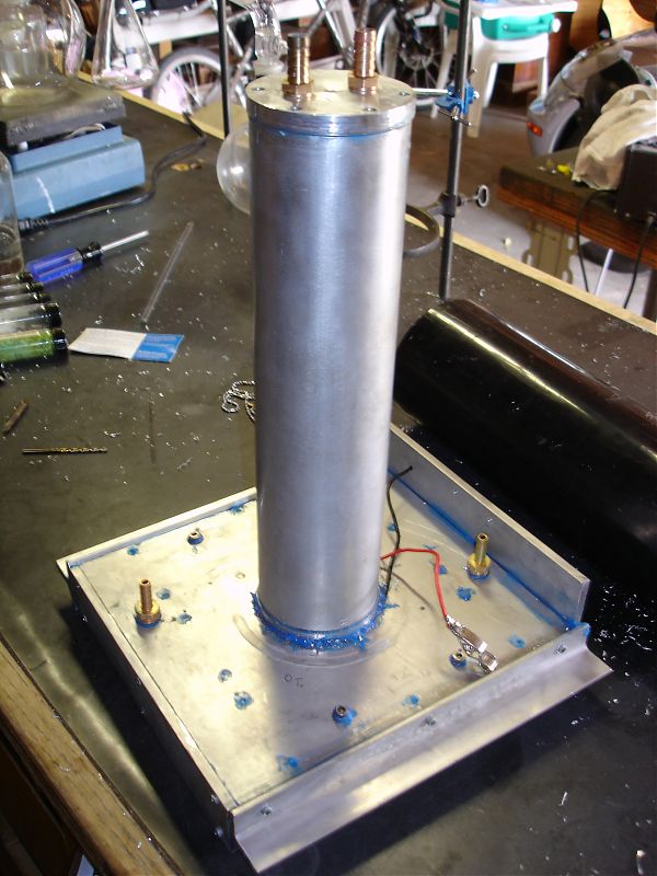
The second upgrade was the insulation jacket. There has been a crude version of this in use since I finished the unit, but now it actually looks decent and the minimum temp dropped somewhat. The spaces around the peltier element have been filled by silicone adhesive.
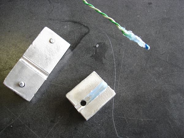
The last upgrade are the two thermoresistive sensors that were installed. One at the top of the cooler cap (where temps will be highest), and one on the heatsink where the peltier is mounted (where temps will be highest). This will allow my program to have the best odds of protecting the peltier, and maintaining the coolant temperature near the set point. Here are the grooved blocks that hold the sensor against the metal.
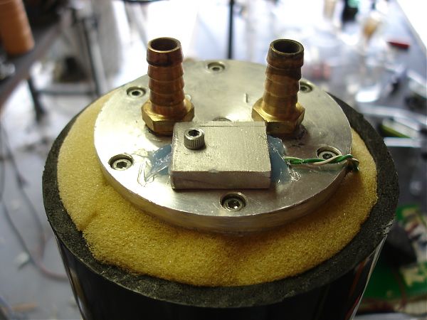
An here is the end-cap with everything in place.
The power supply that I am using for this task is inadequate. It is adjustable to 15v, but at that voltage, it won’t push nearly 26 amps. I have to build a bigger PSU for that. This is a picture of the resistance reading on the coolant-side sensor after the device had been chilling at 5v for about 30 minutes.
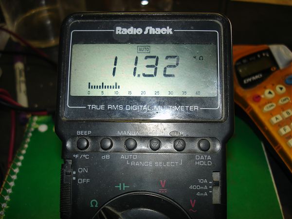
There is about 200mL of water/methanol mix in the chamber. The block does not have water circulating, so lower temperatures will be reached. This reading corresponds to about 19 degrees celcius. More details will be posted once I get a solid PSU and run this thing to capacity.
Update 2010.01.19:
The coolant chiller suffered an unfortunate accident. I dropped it and broke the TEC. I decided that the wide footprint and sketchy mounting of the cylinder were both in need of correction. I used the chance to rebuild the waterblock:

The interface is now a polished copper surface and the water path more evenly contacts the fins of the heat sink. Additionally, the heat sink mounting nuts for the motherboard are going to fit the bracket I made (around the cylinder in the background).
Another picture:
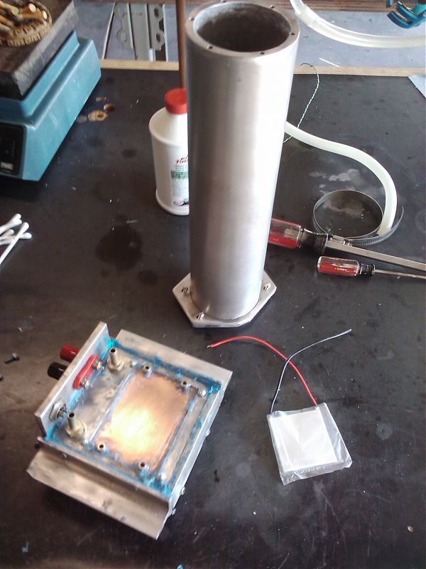
Fully-assembled (without the insulation shroud):
A close-up of the mounting. This should hold the cylinder more securely and prevent uneven strain on the TEC in the event that excessive pressure is applied at a right-angle to the axis of the cylinder.
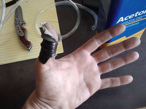
This is what bandages look like when you have better things to do.
The chiller is now permanently mounted and connected to its support hardware. The power supply hasn’t been built (or designed) yet. So the test will still reflect the low power ceiling of the variable supply I have on hand.
Previous: Couldn't bring myself to work indoors today
Next: My first fractal poster