The front panel
2013-09-14 16:40 by Ian
The front panel is the replacement face-plate for the radio box. It is the base of the user interface for the car computer.
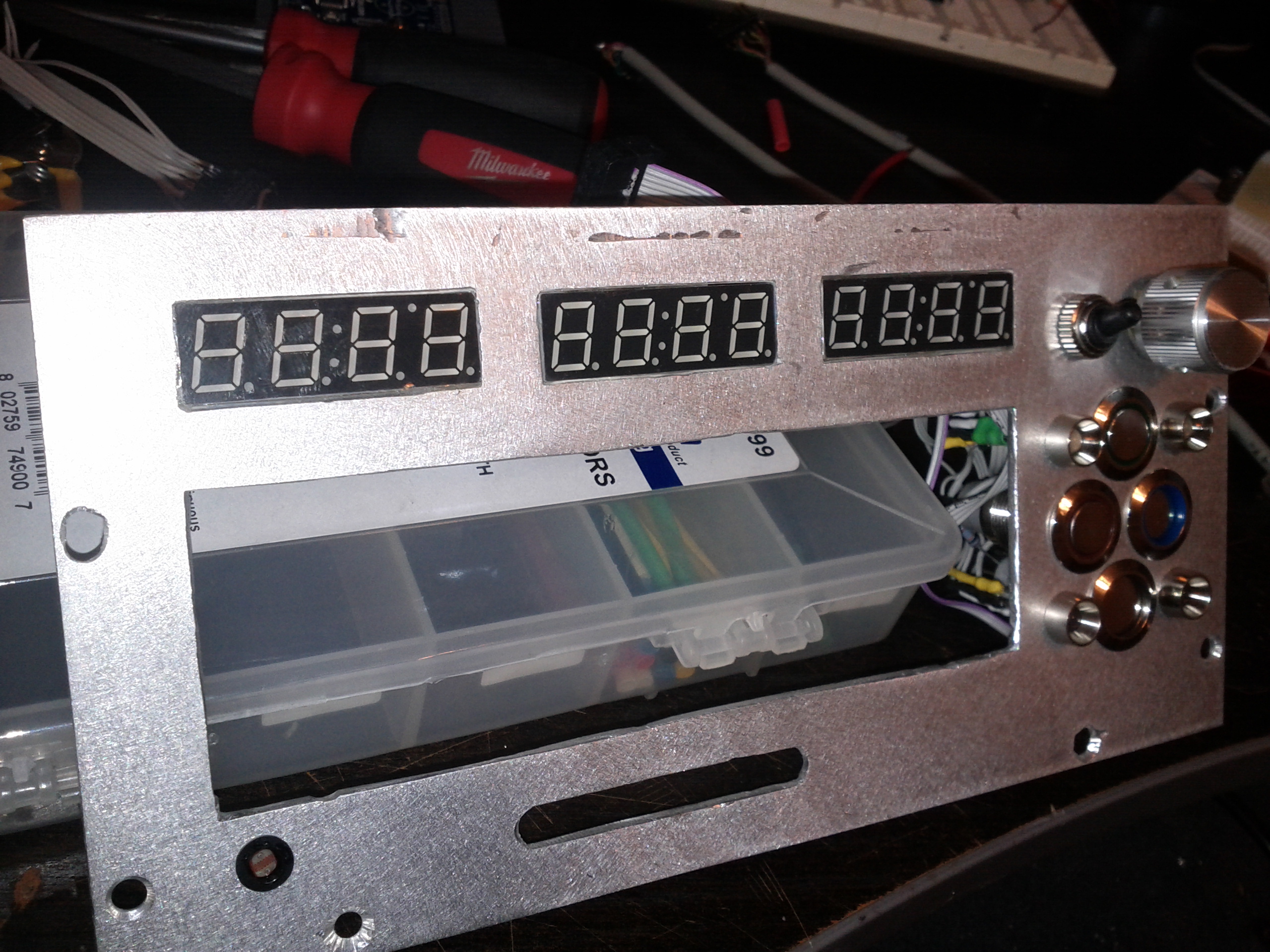
Visible on the face of the panel are the 7-segment LED displays, a toggle switch, a rotary encoder, Four chrome push-buttons (three of them illuminated) four RGB LEDs, and a CdS cell.
The 7-segment LED displays were chosen for their small foot-print, and their readability under wide ranges of angle and ambient brightness. They are being used as SPI devices, each with their own chip-select pin.
All other LEDs on the panel are being driven from a 16-bit shift register. The illumination in the chrome buttons takes 12v, and so, there are 3 NPN transistors configured as low-side switches with their bases tied to output pins on the shift register.
One of the nice features of the 74HCT595 is that it has a serial carry pin that can be used to feed another device. This allows one to make an SPI register of arbitrary length by stringing many 595's together in series. Because all but one of the bus-interface pins are common in this configuration (the one exception being the serial data line), I've taken to stacking them when space is at a premium. Here is the PCB that holds the shift registers and the transistors that drive the 12v LEDs on the panel:

The chrome buttons are tied together in a resistor ladder, and are meant to be read by one of the the microcontroller's analog input pins.
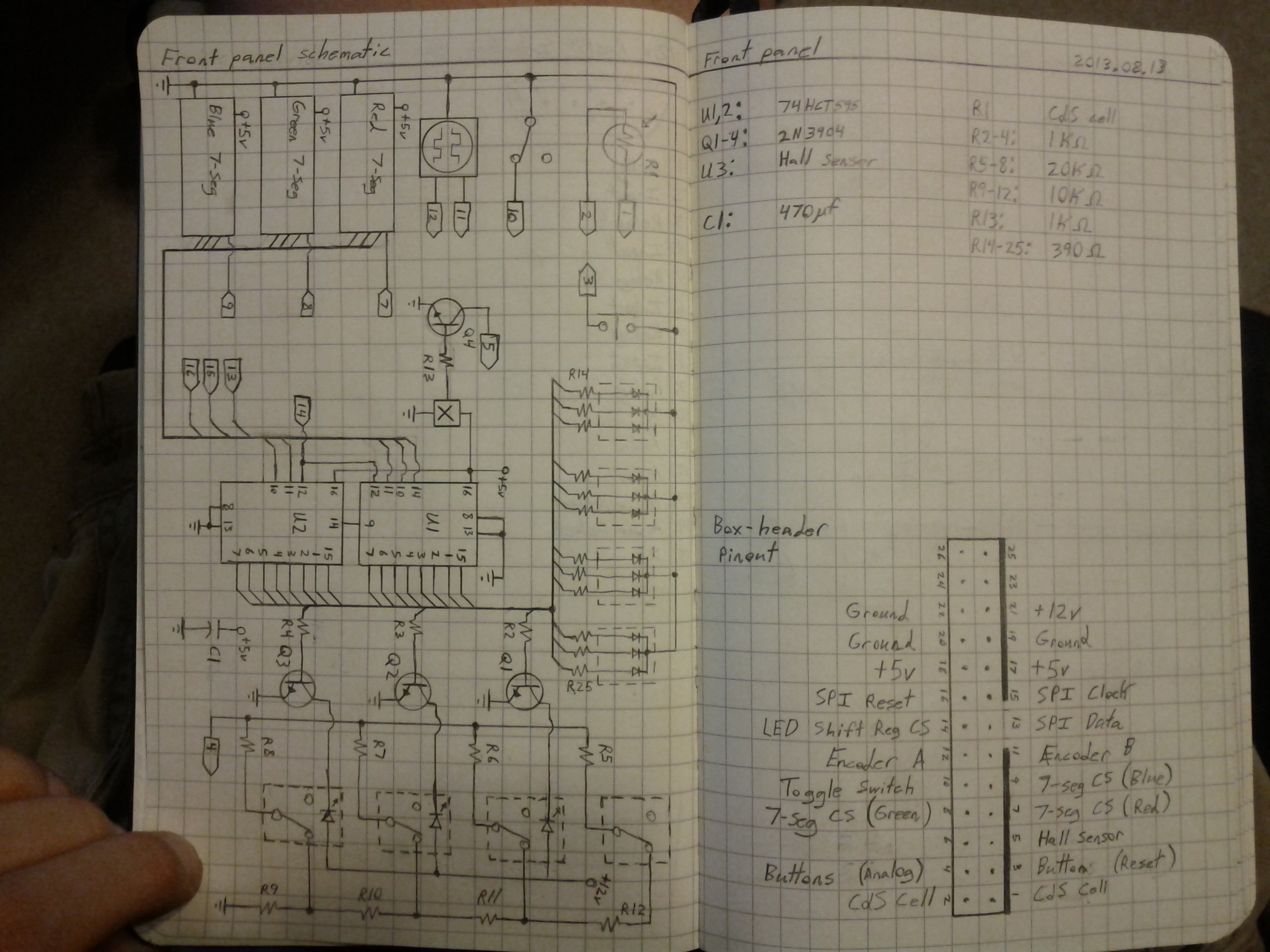
The schematic and some of my construction notes for the front panel are given below:
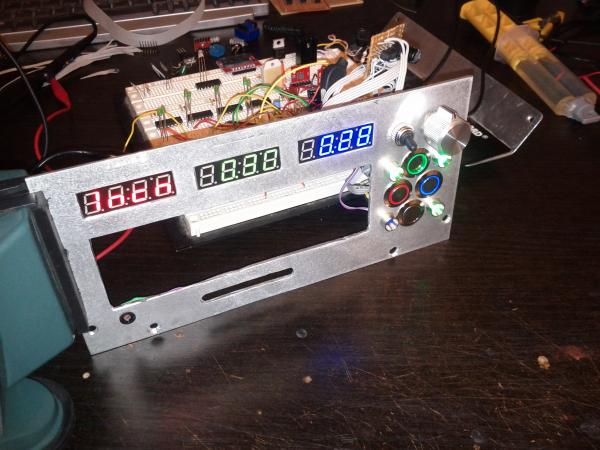
Here is the completed front panel attached to the (still breadboarded) main PCB:
Previous: Locker Override and Undercarriage Lighting
Next: Secondary battery and isolator installation